2017 The 122nd Canton fair
We are professional manufacturing and trading enterprise of various kinds of bags and luggages for outdoor and daily use with more than 15 years production experience. We
We are professional manufacturing and trading enterprise of various kinds of bags and luggages for outdoor and daily use with more than 15 years production experience. We
In the wire and cable industry, accurate and reliable quality testing is an important link to ensure product performance and safety. Tophung is an enterprise specializing in the production of wire and cable testing equipment, and has long served many cable companies at home and abroad to explore the quality testing solutions of cable products in an all-round way. In the wire and cable industry, our main products are: TH-5806 Cable Bending testing machine, TH-5807 Cable 2D torsion testing machine, TH-5812 Cable vertical torsion testing machine, TH-5813 Cable drag chain bending testing machine, TH-5814 Cable 3D torsion testing machine, etc., these machines can be obtained from different repeated experiments. Detects the cable's performance of plastic deformation and displays its own defects.
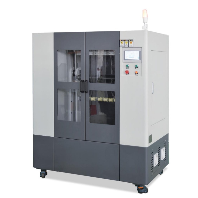


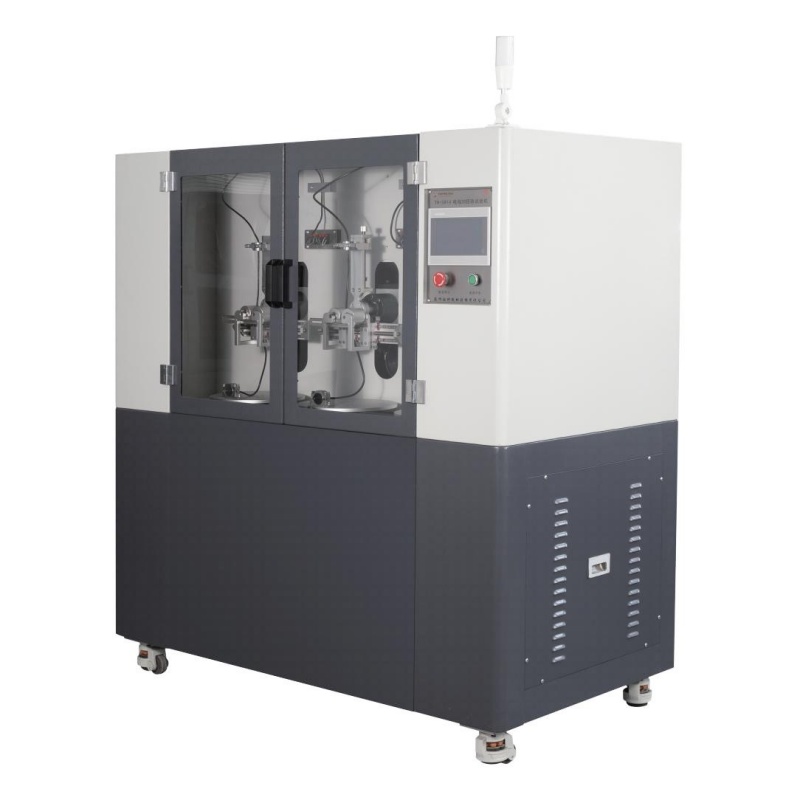
Our company offers wire and cable bending testing equipment with a variety of flexible functions and technologies, enabling manufacturers to achieve comprehensive quality control and product improvement. Here are a few highlights of our diverse testing:
1. Multi-angle bending test: Our equipment can simulate the use conditions of wire and cable at different angles, and ensure the reliability and durability of products through bending test at various angles. This helps manufacturers identify potential bending damage and failure points in advance to avoid subsequent problems caused by bending and improve product reliability and user satisfaction.
2. Accurate bending radius measurement: Our equipment uses advanced measuring technology to accurately measure the bending radius of wire and cable. By monitoring the change of bending radius, manufacturers can adjust the production process in time, and maintain consistent bending performance in the quality control process, to avoid product quality problems caused by too large or too small bending.
3. Dynamic bending simulation: Our equipment can simulate the dynamic bending of wire and cable in actual use. By conducting dynamic bending tests on products, manufacturers can better understand the performance of wire and cable under motion and vibration conditions, further optimize the structure and material of the product, and improve the reliability and durability of the product.
Our wire and cable bending testing equipment helps manufacturers to improve product quality, improve production efficiency and enhance market competitiveness. We are committed to providing the most advanced inspection solutions for the wire and cable industry, helping manufacturers achieve sustainable development and industry leadership.
Tophung - reliable production equipment manufacturers!
ASTM (American Society for Testing and Materials) machines are specialized testing instruments designed to evaluate the mechanical and physical properties of materials according to ASTM standards. These machines play a crucial role in ensuring the quality, safety, and performance of materials used in various industries, including metal manufacturing, new composite materials, solar photovoltaic energy, wire and cable, automotive, and plastics.
At Suzhou TOPHUNG Machine Equipment Co., Ltd., we specialize in the research, development, production, sales, and service of high-quality ASTM testing machines. Our advanced testing equipment ensures that materials meet the rigorous requirements set by ASTM, enabling manufacturers to maintain consistency, reliability, and compliance with international quality standards.
ASTM testing machines come in various types, depending on the specific property being tested. Some common categories include:

ASTM machines are essential for material quality assessment and compliance with international standards. At Suzhou TOPHUNG, we are committed to providing cutting-edge testing solutions that help businesses enhance product quality, reduce risks, and improve competitiveness in global markets. Whether you need material mechanics testing, photovoltaic testing, or cable testing machines, our team is ready to support you with top-notch equipment and technical expertise.
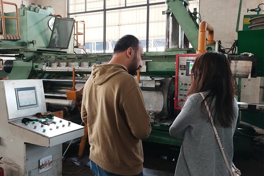
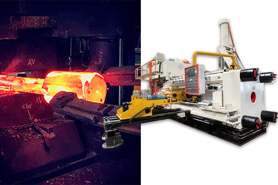
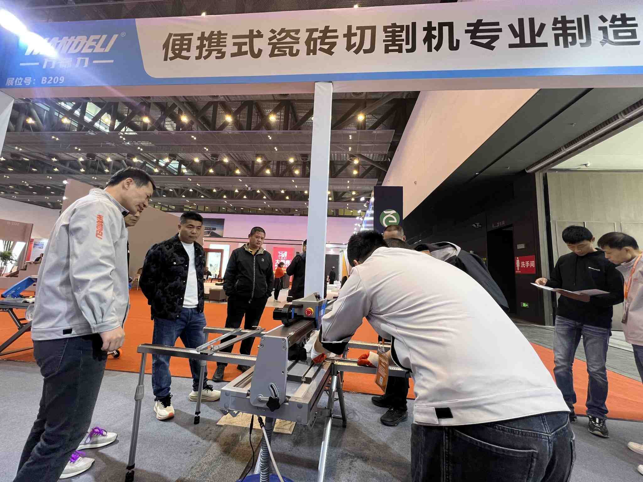
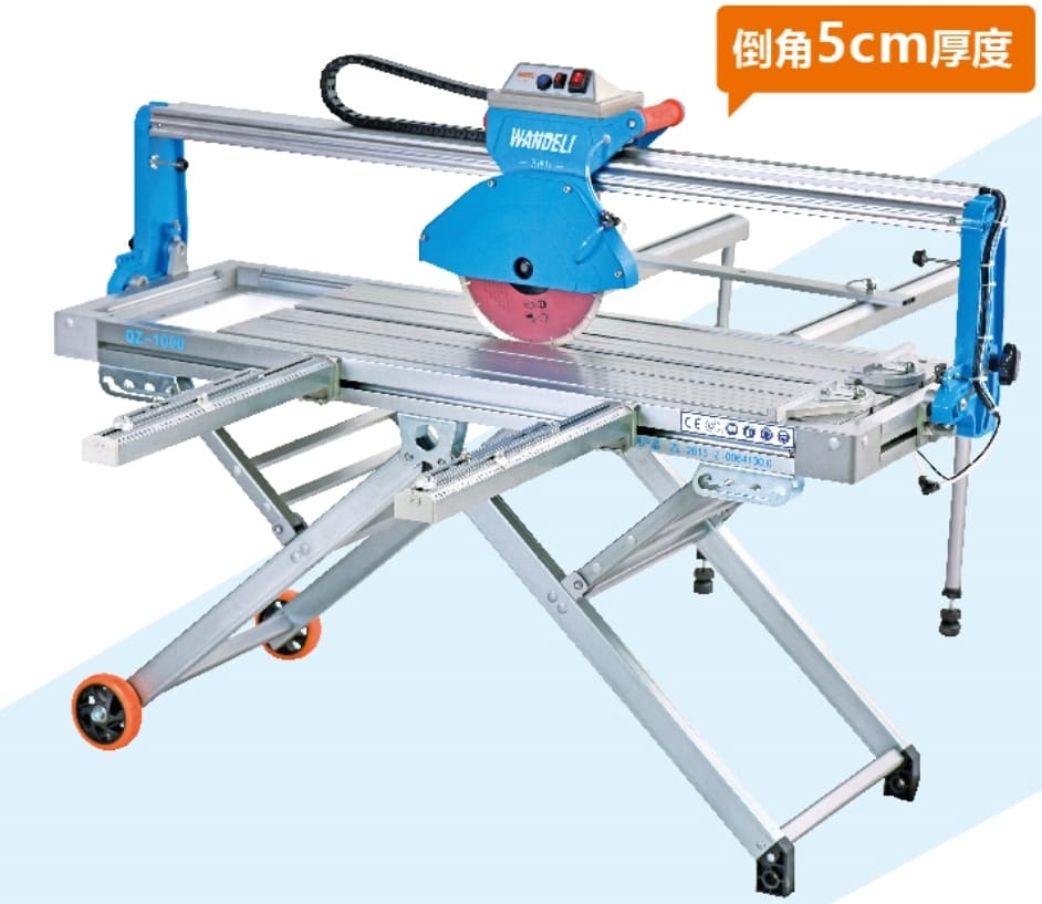
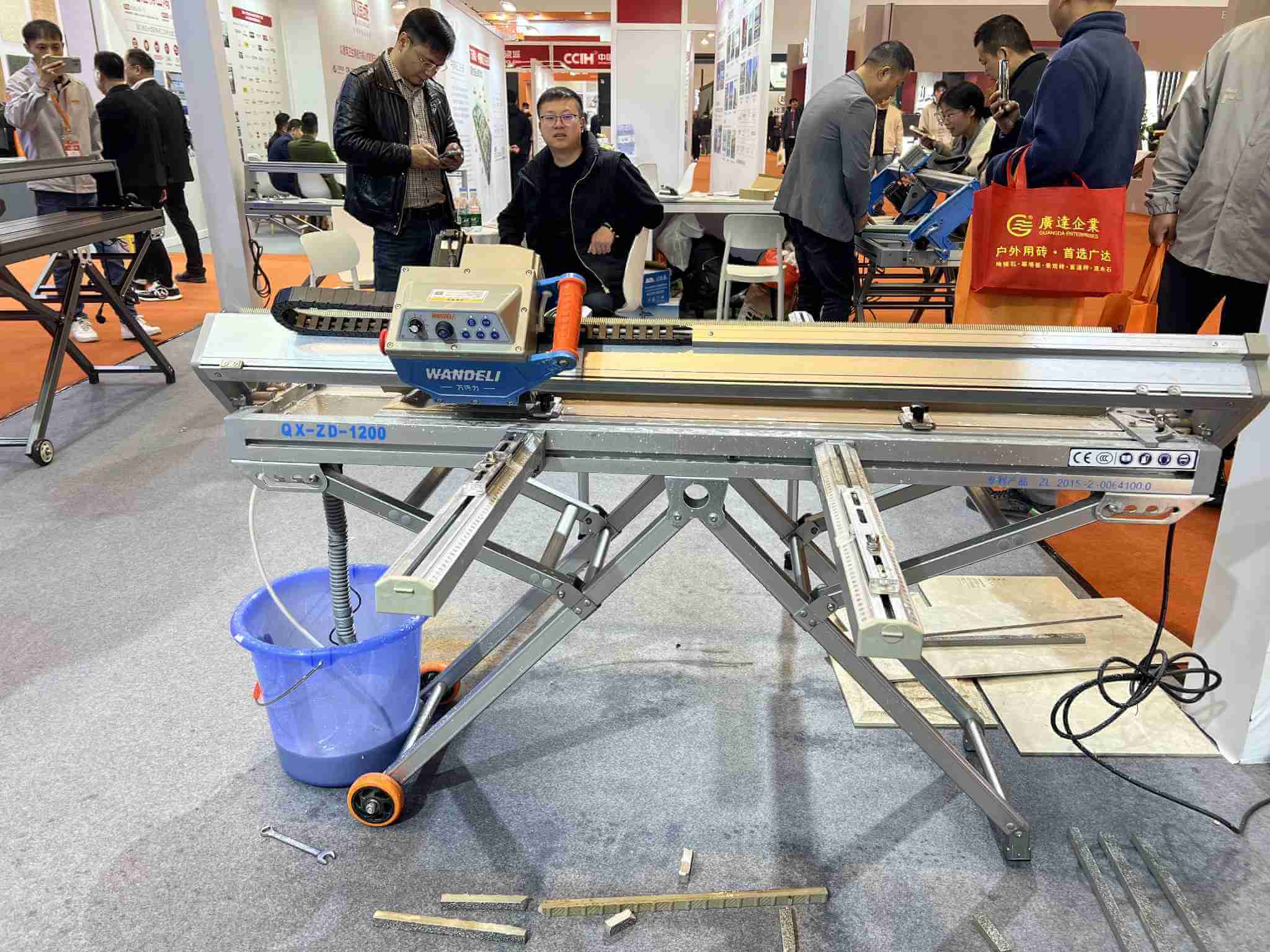
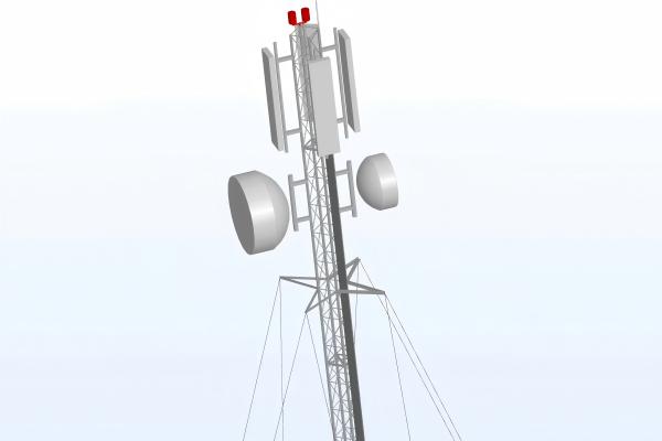
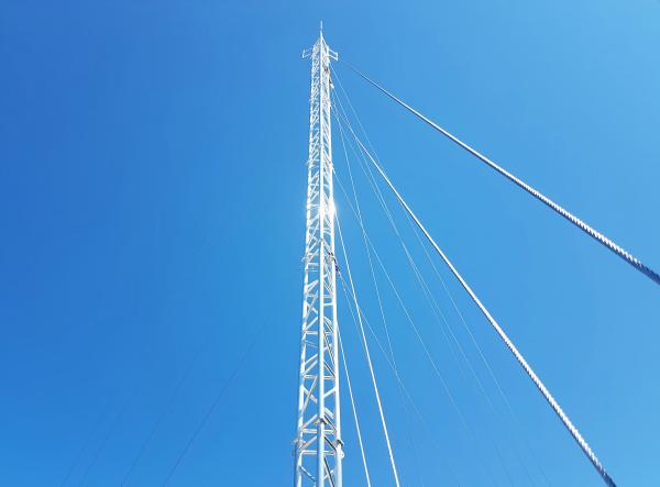
Universal testing machines (utm) play a vital role in various industries by examining the mechanical properties and properties of materials, components and finished products. These versatile machines can perform a wide range of tests, including tensile strength, compression, bending, shearing and more. Suzhou Tophung TOPHUNG's utm is designed with precision and accuracy in mind, ensuring reliable and repeatable test results. With different load capacities and flexible test configurations, it can meet the test needs of different industries. Whether you need to test metal materials, composites, solar panels, wire and cable, automotive parts or plastic products, our utm offers a complete solution. They enable you to assess the durability, strength and integrity of materials and finished products, ensuring compliance with industry standards and regulations. Recently, a client from the Middle East visited our factory and intended to purchase an aluminum extrusion press for manufacturing door and window materials. We recommended the customer to purchase a 5-inch extrusion press, specifically our 1100T aluminum extrusion press. Through our discussion, we realized that the customer had limited knowledge about extrusion presses. Previously, he used to purchase aluminum materials for making doors and windows, but now he plans to buy an extrusion press to produce aluminum materials himself. Someone had suggested that he should buy an 1800T aluminum extrusion press for producing door and window aluminum materials. However, based on the sizes of the door and window materials he needs, we recommended the 1100T aluminum extrusion press instead. Our Huanan 1100T aluminum extrusion press is also a 5-inch aluminum extrusion press, which is suitable for extruding various door and window aluminum profiles. The extrusion cylinder specifications of our 1100T aluminum extrusion press machine are: Diameter: 132mm Length: 800mm Applicable aluminum billet size: Diameter: 127mm Length range: 400–750mm When extruding aluminum, it is crucial to consider the extrusion pressure. If the extrusion press tonnage is too high relative to the aluminum billet diameter and alloy type, the following issues may occur: Excessive Metal Flow Rate: Too much pressure can cause excessively fast metal flow, affecting dimensional accuracy and surface quality. Overheating: Excessive extrusion pressure can lead to rapid temperature rise, potentially causing surface roughness, cracks, or even burning. Shortened Die Lifespan: Excessive pressure may exceed the die’s load capacity, leading to rapid wear or even breakage. Die Deformation: Continuous use of an overpowered press can cause plastic deformation of the die, affecting profile accuracy. Accelerated Extrusion Cylinder Wear: Higher pressure accelerates wear on the inner wall of the extrusion cylinder, shortening its lifespan. Hydraulic System Overload: If the tonnage is too high, the hydraulic system may overheat, experience pressure failures, or even develop leaks. Coarse Grain Structure: Excessive extrusion speed can lead to larger metal grains, reducing mechanical performance. Increased Defects: High stress and temperature may introduce bubbles or inclusions inside the aluminum, affecting product quality. Reduced Dimensional Accuracy: Overpowering the extrusion process may lead to unstable profile dimensions and out-of-tolerance products. Higher Energy Consumption: A high-tonnage extrusion press consumes more energy, leading to unnecessary waste if the press is oversized. Increased Maintenance Costs: Faster wear and tear on molds, extrusion cylinders, and hydraulic systems lead to higher maintenance and replacement costs. When purchasing an aluminum extruder, it is essential to determine the size of the aluminum profiles to be produced and ensure that the press tonnage is appropriate. For those who are new to the industry and considering purchasing an extrusion press, you can contact our sales team at Huanan Heavy Industry via WhatsApp or Email. Our sales team is highly knowledgeable about extrusion presses and can consult with engineers to provide professional guidance. WhatsApp: +86 13450865812Email: jessica@huananmachine.com Finally, we took our Middle Eastern client to the production line to observe the entire mechanical production process and inspect the 5-inch aluminum extrusion machine in action. This helped the customer better understand the Aluminum extrusion process and the necessary machinery, giving him a clearer view of the entire aluminum manufacturing process. The similarities and differences between copper extrusion and aluminum extrusion Aluminum is one of the most common materials in our daily lives and an essential metal in various industries. However, in addition to aluminum, copper is also a widely used metal due to its excellent electrical and thermal conductivity, corrosion resistance, and other favorable properties. Copper has broad applications across multiple industries, such as: Electrical and Electronics: Wires, cables, transformers, motors, and electronic components. Construction: Piping systems, electrical wiring, and copper conductors. Automotive: Electrical systems, radiators. Industrial Equipment: Heat exchangers, valves, pumps, bearings, and gears. Telecommunications: Cables. Energy: Solar panels, generators. Healthcare: Medical devices, surgical instruments, door handles, and handrails due to its antibacterial properties. Both aluminum and copper are produced through extrusion processes, where pressure is applied to metal billets, forcing them through molds to form the desired shapes. While the basic production process is similar for both materials, copper and aluminum differ significantly in their properties, which affects their production methods and equipment. Production Process: Both aluminum and copper extrusion processes involve applying hydraulic or mechanical pressure to metal billets, which are heated to increase their plasticity for easier extrusion. The extrusion equipment, including extrusion cylinders, molds, extrusion rods, and heating systems, are similar for both metals. However, because copper and aluminum have different properties, the specific production conditions, such as temperature and pressure, vary. Differences Between Aluminum and Copper: Aluminum: Density: Low Melting Point: Approximately 660°C Plasticity: High, making it easier to extrude Extrusion Pressure: Relatively low Copper: Density: High Melting Point: Approximately 1085°C Hardness: Higher, making extrusion more difficult Extrusion Pressure: Higher due to its hardness Because of these differences, the heating temperature required for aluminum and copper extrusion is not the same. For aluminum, the heating temperature typically ranges from 400°C to 500°C, while for copper, it is generally higher due to its higher melting point. This difference in properties also results in copper requiring higher extrusion pressures compared to aluminum. This is one of the reasons why our HuaNan heavy Industry can produce copper extruders in addition to aluminum extruders. Molds: Mold material plays a crucial role in determining the extrusion quality. Aluminum extrusion molds are usually made from high-strength steel, offering durability. Copper extrusion molds, on the other hand, require materials with higher wear and heat resistance, making them less durable than aluminum molds. Lubrication: The choice of lubricant also differs. Aluminum extrusion typically uses graphite or oil-based lubricants, while copper extrusion requires high-temperature lubricants such as glass lubricants to manage the higher extrusion pressures. Cooling: After extrusion, cooling methods vary. Aluminum cools faster and is typically cooled using air or water, while copper requires a slower, gentler cooling process to prevent cracking. Post-Treatment: Aluminum often undergoes anodizing or spraying treatments, while copper is usually treated through electroplating or polishing to achieve a smooth finish. Production Costs: Despite similar production processes, the costs of extruding copper are generally higher than for aluminum due to copper's higher extrusion pressures and material costs. Summary: In conclusion, while the extrusion processes for aluminum and copper are fundamentally similar, the differences in their material properties lead to distinct requirements for heating, extrusion pressure, mold materials, lubrication, cooling, post-treatment, and cost. Copper extrusion typically involves higher pressures, more specialized molds, and more complex handling, which results in higher production costs compared to aluminum extrusion. Forging and casting are two common metalworking processes, each with its own advantages and disadvantages, suitable for different applications. Let’s start by looking at the benefits of forging over casting: Higher Strength: During the forging process, the grain structure of the steel is compressed and refined, enhancing its strength and toughness. Better Fatigue Performance: Forged parts can withstand repeated stresses, making them ideal for high-load and dynamic stress applications. Fewer Internal Defects: Forging reduces defects such as porosity and shrinkage, improving the material’s density and overall quality. High Dimensional Precision: Forged parts have precise dimensions, requiring minimal post-processing, which saves both material and time. At Huannan Heavy Industry, we use forging for the main components of our aluminum extrusion machines, including the front beams, tension columns, extrusion rods, and extruder container. This allows our machines to better withstand the impact forces during extrusion. In contrast, many competitors use cast steel for components like the front beam and tension column. The drawback of casting is that the material’s strength is lower due to a coarser grain structure, and casting is more prone to internal defects like porosity and shrinkage. These defects can weaken the material and affect its overall performance. Aluminum extrusion machines made with cast steel are more likely to suffer from insufficient toughness and strength, making them prone to damage under prolonged operational pressure. While casting is more cost-effective, the quality simply cannot match that of forged steel. This is why our extrusion machines may be priced higher than those of our competitors, but the superior quality and longer service life make them a much better investment in the long run. This is the confidence we have in Huannan Heavy Industry’s aluminum extrusion machines—our commitment to quality sets us apart. In a chemical leak at a BASF plant in Germany, the failure of a traditional mechanical seal pump resulted in €12 million in equipment losses and triggered a 72-hour environmental pollution alert. This incident directly accelerated the global industry's adoption of magnetic drive pumps. According to a 2024 study by the International Journal of Chemical Safety, the widespread use of magnetic drive pumps has reduced global industrial leaks by 63% and reduced carbon emissions by about 4.5 million tons per year. This innovative technology based on magnetic coupling is reshaping the modern industrial fluid transmission paradigm with the advantages of zero leakage and high efficiency. 1. What is a magnetic drive pump? A magnetic drive pump is a sealless pump that transmits power through magnetic field coupling. Its core design eliminates traditional mechanical shaft seals. According to the ISO 2858 standard definition, a magnetic drive pump uses an isolation sleeve to separate the inner and outer magnetic rotors, and uses rare earth permanent magnets (such as neodymium iron boron or samarium cobalt) for non-contact power transmission, completely eliminating the risk of leakage. The technology was named one of the "Top Ten Industrial Safety Innovations of the 21st Century" by ASME magazine and is ideal for conveying corrosive, toxic or high-purity media. 2. How does a magnetic drive pump work? The operation of a magnetic drive pump relies on synchronous magnetic coupling: 1. Power transmission: The motor drives the outer magnetic rotor, and the magnetic field of the outer magnetic rotor penetrates the isolation sleeve (usually made of silicon carbide or Hastelloy) and rotates the inner magnetic rotor synchronously. 2. Medium transportation: The inner rotor is connected to the impeller and uses centrifugal force to move the liquid from the suction port to the discharge port. 3. Sealing mechanism: The isolation sleeve and the static seal form a double barrier to ensure that the medium is completely sealed. 3. Advantages and disadvantages of magnetic drive pumps Advantages: Zero leakage safety: Eliminates 99.7% of the risk of leakage (verified by API 685 standard), which is an ideal choice for hazardous media such as hydrofluoric acid and liquid chlorine. High energy efficiency: The magnetic transmission efficiency reaches 98%, which saves 15%-20% energy compared with mechanical seal pumps. Low maintenance cost: No dynamic seal, maintenance interval extended to 3-5 years Disadvantages: High initial cost: The price is 30%-50% higher than that of traditional pumps, mainly due to the cost of rare earth magnets (accounting for 35% of the total cost). Media restrictions: Poor adaptability to liquids containing solid particles (>50μm) or high viscosity (>500cP). Temperature sensitivity: Neodymium magnets demagnetize above 120°C and need to be upgraded to samarium cobalt magnets. 4. Application areas Chemical and petrochemical: Transporting corrosive media such as hydrochloric acid and aniline. Pharmaceutical and biotechnology: Aseptic vaccine filling lines that meet USP Class VI purity standards. New energy and environmental protection: Liquid hydrogen circulation system for fuel cells, resistant to ultra-low temperatures (-253°C). Microelectronics manufacturing: Ultrapure water delivery, particle contamination control <0.1μm. 5. How to choose a suitable magnetic drive pump? 1. Medium characteristics: pH, viscosity and solid content determine the choice of materials (for example, strong acids use PTFE lining). 2. Performance parameters: Flow (Q), head (H) and NPSHr (net positive suction head required) in accordance with ANSI/API 685. 3. Temperature range: Custom designs for extreme conditions (-112°C to 800°C) (e.g. double-layer isolation sleeve). 4. Certifications: ISO 9001 quality system and ATEX explosion-proof certification for hazardous environments. 6. Maintenance tips Preventive maintenance strategy: Monthly inspection: Measure the magnetic coupling air gap (standard: 1.5-3mm) and bearing wear (vibration <2.8mm/s). Quarterly maintenance: Clean the impeller channel to prevent crystallization (e.g. sodium hydroxide accumulation). Annual overhaul: Replace the isolation sleeve if the thickness wear exceeds 0.2mm. 7. Common faults and troubleshooting Magnetic drive pumps redefine the boundaries of industrial safety with revolutionary technology. Choosing the right magnetic drive pump is not just an equipment investment, but a strategic commitment to a sustainable future. For expert advice on magnetic drive pump selection, contact Changyu Pumps & Valves - we offer tailor-made solutions to suit your needs. Wandel Machinery, a leader in innovative construction equipment, is revolutionizing the tile-cutting industry with its latest launch: the 3000W brushless motor tile cutting machine. Showcasing models like the QXZ-ZD-1600, QX-1000, GT-AT-1200, QZ-1000, and the acclaimed QX Series & QXZ Series at their booth, Wandel Machinery combines power, precision, and energy efficiency to meet the demands of modern construction projects. Why the 3000W Brushless Motor Technology Stands Out The star of Wandel Machinery’s booth is the 3000W brushless motor, engineered for high-performance tile cutting. Unlike traditional motors, brushless technology ensures longer lifespan, reduced maintenance, and 30% higher energy efficiency. This motor powers through dense materials like porcelain, ceramic, and natural stone with ease, making it ideal for heavy-duty industrial applications. Spotlight on Featured Models: Precision Meets Versatility QXZ-ZD-1600: Designed for industrial-grade precision, this model features a 1600mm cutting capacity and laser-guided accuracy. Its anti-vibration design ensures smooth operation, while the dust-proof brushless motor enhances durability. QX-1000: Compact yet powerful, the QX-1000 is perfect for smaller job sites. Its 1000mm cutting range and user-friendly interface make it a favorite for contractors seeking portable, high-efficiency tools. GT-AT-1200: Built for versatile applications, this model boasts a 1200mm cutting length and adjustable angle settings for complex cuts. The auto-shutoff safety feature adds an extra layer of protection. QZ-1000: Optimized for speed and accuracy, the QZ-1000 includes a quick-clamp system and water-cooled motor to prevent overheating during prolonged use. QX Series & QXZ Series: Redefining Tile Cutting Solutions Wandel Machinery’s QX Series and QXZ Series are engineered to deliver unmatched performance. The QX Series focuses on portability and ease of use, ideal for residential projects, while the QXZ Series offers heavy-duty capabilities for large-scale commercial jobs. Both series feature brushless motor technology, ensuring quieter operation and lower energy consumption. Visit the Wandel Machinery Booth: Experience Innovation Firsthand At their booth, Wandel Machinery invites visitors to witness live demonstrations of the QXZ-ZD-1600, QX-1000, and other models in action. Explore how their cutting-edge technology improves workflow efficiency and reduces operational costs. Experts will be available to discuss custom solutions tailored to your project needs. Elevate Your Projects with Wandel Machinery Wandel Machinery continues to set industry benchmarks with robust, energy-efficient tile cutting machines. Whether you’re tackling a kitchen renovation or a high-rise construction, models like the QXZ-ZD-1600 and QX Series provide the power, precision, and reliability professionals trust. Don’t miss the chance to see these game-changing tools at their booth—where innovation meets craftsmanship. Telecom towers vary in design, each suited to specific environments and requirements. Here's a structured comparison of guyed wire towers with other common types (lattice, monopole, stealth, and self-supporting towers): Guyed Wire Towers: Tallest (200–600+ meters), ideal for extensive coverage in rural areas. Lattice Towers: Moderate height (60–200 meters), self-supporting with robust frameworks. Monopoles: Shorter (30–60 meters), suited for urban/suburban areas. Stealth Towers: Height-limited (similar to monopoles), prioritizing aesthetics over height. Guyed: Lower material costs due to wire support but may incur higher land/installation expenses. Lattice: Moderate cost, more material-intensive than guyed. Monopoles: Higher cost per meter due to thick steel/concrete construction. Stealth: Most expensive due to custom designs (e.g., faux trees). Guyed: Large footprint (anchor points extend 30–60% of height), unsuitable for dense areas. Lattice: Moderate base area, no guy wires. Monopoles: Minimal ground space, ideal for cities. Stealth: Similar to monopoles, with added space for disguises (e.g., fake branches). Guyed: Complex installation (anchoring wires), higher maintenance (wire tension, corrosion). Lattice: Modular assembly, moderate maintenance (joint inspections). Monopoles: Quick installation, low maintenance (simple structure). Stealth: Installation varies; maintenance includes aesthetic upkeep. Guyed: Vulnerable to wire damage/vandalism; anchors may shift in soft soil. Lattice: Highly durable in extreme weather (wind/ice). Monopoles: Robust but height-limited; less wind-resistant at greater heights. Stealth: Materials (e.g., fiberglass) may degrade faster than steel. Guyed: Rural/remote areas, long-distance communication, broadcast. Lattice: Broadcast, moderate-height cellular networks. Monopoles: Urban cellular networks, small cells. Stealth: Residential/Scenic areas (parks, historic sites). Guyed: Least visually appealing; zoning challenges due to land use. Lattice: Industrial appearance but less intrusive than guyed. Monopoles: Slim profile, easier urban permitting. Stealth: Blends into surroundings; preferred in sensitive areas. Guyed: Limited by wire tension; harder to modify. Lattice: Easily expanded with additional antennas. Monopoles: Limited capacity; may require replacement for upgrades. Stealth: Design constraints limit expansion. Guyed: Higher land disturbance for anchors. Lattice/Stealth: Lower ecological impact (smaller footprint). Conclusion: Guyed wire towers excel in cost-effective height for rural coverage but require significant space and maintenance. Monopoles and stealth towers prioritize urban aesthetics, while lattice towers balance durability and moderate height. The choice depends on height needs, budget, location, and visual requirements. Learn more at www.alttower.com


Middle Eastern Client Visit and Aluminum Extrusion Press Recommendation
Considerations When Extruding Aluminum: Extrusion Pressure
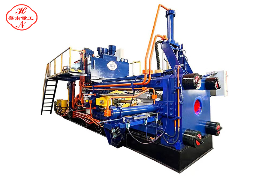
1. Over-Extrusion
2. Mold and Die Damage
3. Equipment Damage
4. Negative Impact on Product Quality
5. Increased Production Costs
Choosing the Right Extrusion Press
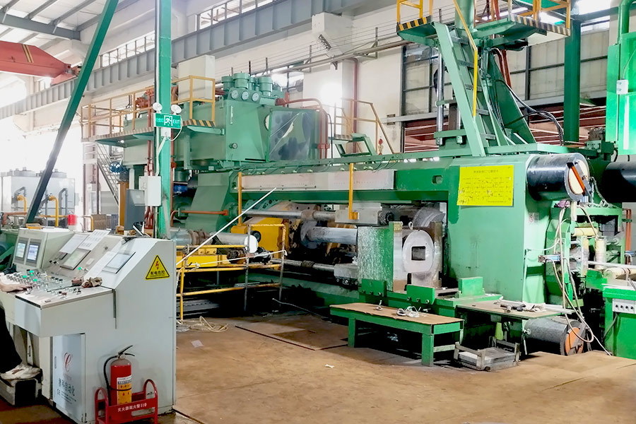
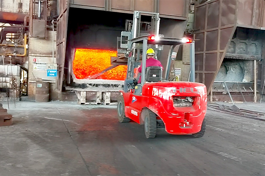
The similarities and differences between copper extrusion and aluminum extrusion
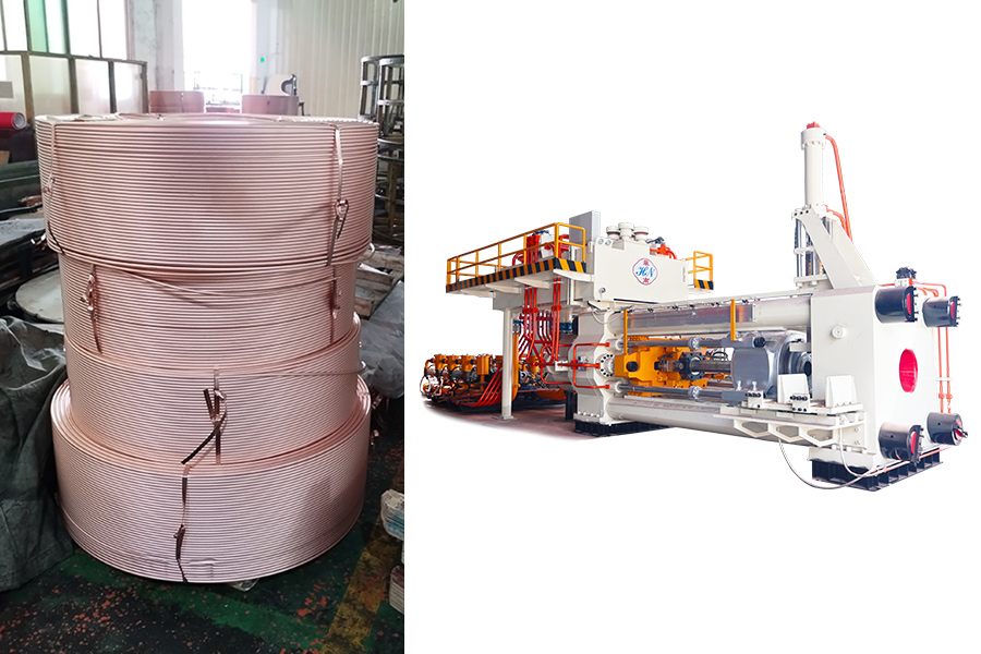
Why We Are Confident in Our Aluminum Extrusion Machines
Zero Leakage Technology, Why Magnetic Drive Pump?


Wandel Machinery Unveils Cutting-Edge 3000W & 4500W Brushless Motor Tile Cutting Machines Discover the QXZ-ZD-1600, QX Series & More
Comparison of Guyed Wire Telecom Towers with Other Tower Types
1. Height Capacity
2. Cost
3. Space Requirements
4. Installation & Maintenance
5. Durability & Reliability
6. Applications
7. Aesthetics & Zoning
8. Expandability
9. Environmental Impact
Summary Table:
Feature
Guyed Wire
Lattice
Monopole
Stealth
Max Height
200–600+ m
60–200 m
30–60 m
30–50 m
Cost
Low (materials)
Moderate
High per meter
Highest
Space
Large (guy anchors)
Moderate base
Minimal
Minimal + aesthetics
Maintenance
High (wires)
Moderate
Low
Moderate-High
Durability
Moderate (wire risks)
High
High
Variable
Best Use
Rural, broadcast
Broadcast, cellular
Urban cellular
Scenic/Urban areas

